Heat Treatment Cooling Medium Overview
Generally, the heat treatment cooling medium includes quenching cooling medium, annealing cooling medium, normalizing cooling medium, tempering cooling medium, etc. Since the annealing cooling medium and the normalizing cooling medium are mostly air medium, this book mainly introduces quenching cooling. Media and tempering cooling media.
Quenching and cooling process
According to the quenching and cooling process of the workpiece, whether the quenching medium changes state of matter, the quenching medium is divided into two types, that is, there are changes in the state of matter and no change in the state of matter.
Water, inorganic aqueous solution, organic polymer aqueous solution, various quenching oils, etc., change state of matter during quenching, and gas, molten metal, molten salt, molten alkali, metal plate, etc., do not occur in the state of quenching. Variety.
When the hot steel is quenched and cooled in a quenching medium having a change in state, the cooling process is divided into three stages.
(1) At the moment when the workpiece enters the medium at the vapor film stage, the surrounding medium is immediately heated and vaporized to form a vapor film on the surface of the workpiece. Due to the poor thermal conductivity of the film, the cold speed of the workpiece surrounded by it is very slow. In the initial stage, the film wall is continuously thickened because the heat released by the workpiece is greater than the heat absorbed by the medium from the vapor film. As the cooling process progresses, the temperature of the workpiece continues to decrease, and the thickness and stability of the membrane wall gradually decrease until it breaks and disappears. This is the first stage of cooling.
(2) In the boiling stage, when the vapor film breaks, the workpiece is in direct contact with the medium, the medium is intensely boiling on the surface of the workpiece, and the continuously escaping bubbles take a large amount of heat, so that the cooling rate of the workpiece is large. This phase is until the second stage of cooling until the workpiece cools to the boiling point of the medium.
(3) Convection stage When the workpiece is cooled to below the boiling point of the medium, it can only be cooled by convection heat transfer. The cooling rate of the workpiece is even slower than that of the vapor film stage, and the temperature difference between the surface of the workpiece and the medium is constant. Reducing the cooling rate is getting smaller and smaller, which is the third stage of cooling.Quenching medium cooling performance test
1. Metallurgy method (1) The direct hardness method is to directly determine the hardness of a sample or a workpiece to determine the cooling ability of the quenching medium, which is a conventional method of use. Assuming the process conditions are the same and the samples are the same, the hardness of the workpiece represents the cooling capacity of the quenching medium.
(2) End quenching test method China national standard GB 225-63 "Structural steel end hardenability test method" Under the standard test conditions, the lower end of the sample is sprayed and quenched with water column, the hardness of the surface is measured, and the hardness is drawn to the quenching end face distance. The curve is called the end quenching curve. Different quenching media are used instead of water jet, and the measured end quenching curve can be used to evaluate the cooling capacity of the quenching medium. However, few people have used the end quenching curve to evaluate the quenching medium, but it is still used in the refining of steel.
(3) Hardness U-curve method After quenching a sample having a length of 5 times the diameter, a piece of the sample is cut from the middle. The hardness is measured along the vertical diameter direction on the measurement surface, and the hardness/the curve to the center distance of the sample is plotted with their average values, which is called the hardness U curve. The material and size of the sample are unchanged, the heat treatment process is unchanged, and quenching with different quenching media, the hardness U curve obtained is the basis for evaluating the cooling capacity of the quenching medium. This method is still in widespread use, especially in the process of quenching media.
(4) Quenching intensity method The quenching intensity is also called H value. The H value is defined as follows:
H=C/2K
Where C is the heat dissipation coefficient of the sample, which is defined as follows:
H = Q / S (TW-TL) â–³ t
Where Q is the heat moving from the sample to the quenching medium during the time interval Δt; S is the surface area of ​​the sample in contact with the quenching medium; TW is the temperature of the surface of the sample; TL is the temperature of the quenching medium; Δt is the time interval. The unit of C is kcal / (m ^ 2 · h · ° C); K is the thermal conductivity of the sample, and the K value for carbon steel and low alloy steel is almost a constant. The H value of the commonly used quenching medium is shown in Table 1-1.Table 1-1 H value of commonly used quenching medium
2. Thermodynamic method (1) Magnetic quenching method This is the American national standard ANSI-D 3520-76 "Standard test method for quenching time of heat treatment liquid (magnetic quenching method)". A chrome-plated nickel ball heated to a temperature of (885 ± 6) ° C and a diameter of φ (22.22 ± 0.13) mm was placed in a test solution at 21 to 27 ° C, and the nickel ball was cooled from 885 ° C to a Curie point of 354 ° C of nickel. The time, compared with the cooling time of the standard solution (USP US Pharmacopoeia white oil), find the relative cooling index:
RCL%=cooling time of standard solution/average cooling time of test solution×100
(2) Thermocouple cooling curve method This is currently the best laboratory method, and the ISO 9950 standard is based on this. From the 1940s, Rose, Germany, first used a Φ20mm silver ball as a probe. Later, many probes were developed in various countries. For example: France's Φ8mm × 24mm, Φ16mm × 48mm silver column probe; Japan's Φ10mm × 30mm silver column probe; US Φ10mm × 60mm austenitic stainless steel column probe to the British Φ12.5mm Inconel 600 inlaid alloy cylindrical probe.Interpretation of quenching medium cooling curve
Currently three standards are adopted in China. "Method for Determination of Quenching Oil Cooling Characteristics" (ISO 9950), SH/T 0220 "Measurement Method for Heat Treatment Oil Cooling Performance", JB/T 795l "Quenching Oil Intensity - Silver Probe Test Method".
The same points of the above three standard probes are as follows.
1 are thermocouple test probes and are all at the probe geometry center.
2 are all K-type thermocouples.
3 probe shapes are all cylindrical.
The differences between the three probes are as follows.
1ISO is 12.5 mm x 60 mm Inconel 600 nickel based alloy, JB and SH are silver.
2JB is 16mm × 48mm, and SH is 10mm x 30mm.
3ISO is an armored thermocouple with an outer diameter of 1.5 mm and a JB and SH of 0.5 mm.1. ISO 9950 interpretation and evaluation According to ISO 9950, the test results of the cooling performance of a quenching medium should be divided into three parts: cooling curve (including temperature / hour curve and temperature / cooling speed curve), cooling Time and cooling rate. The requirements for ISO reference oil cooling time and cooling rate are shown in Table 1-2. See Table 1-3 for the indicators of ISO reference oil and similar oil.
At present, most of the foreign countries use the cooling rate to evaluate the quenching medium, and the main points are as follows.
1 When the cooling rate of a medium (maximum cooling rate, maximum cooling rate, cooling rate of 300 ° C) is lower than or higher than oil, the cooling capacity of the medium is lower than or higher than oil.Table 1-2 ISO reference oil cooling time and cooling rate requirements

Table 1-3 Indicators for ISO reference oil and similar oil

Note: The flash point of the opening is about 20 to 30 °C higher than the flash point of the closed port.2 The higher the maximum cooling rate, the easier the workpiece to cool away from the nose of the TTT curve and enter the martensite transformation.
3 The greater the maximum cooling rate, the more heat is removed from the probe surface during the boiling phase.
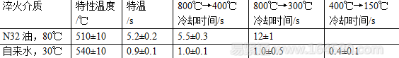
4 The cooling rate at 300 ° C is the main basis for evaluating the cooling performance of the low temperature zone of the medium. When the cooling rate at 300 ° C exceeds 50 ° C / s, it is in principle considered that the water-based quenching liquid is not suitable for replacing oil quenching, because it is easy to cause excessive distortion or even cracking. The quenching oil has a cooling rate of approximately 6 to 30 ° C/s at 300 ° C.2. Interpretation and evaluation of sH/T 0220 standard According to the SH/T 0220 standard, there are two indicators for the evaluation of quenching oil, the characteristic temperature and the time from 800 ° C to 400 ° C. In fact, for fast oil and superbuilders, the time from 800 ° C to 300 ° C is very important. For the evaluation of water-based quenching liquid, it should also be evaluated by cooling time or average speed of cooling at 400 ° C to 150 ° C.
The cooling performance data of N32 oil and water measured according to SH/T 0220 are shown in Table 1-4.Table 1-4 N32 oil and tap water cooling performance
For the evaluation of quenching oil, refer to the technical index of SH 0564-93 "Heat-treated oil".
In the water-based quenching agent, the organic quenching is the main body of the water-based oil medium. There is no uniform method for the evaluation of organic quenching agents in China. In order to prevent excessive distortion and cracking when selecting an organic quenching agent instead of oil quenching, there is a requirement for the cooling performance of the organic quenching agent. ISO 9950 is determined by the cooling rate of 300 ° C. However, it is reasonable to judge the average cooling rate of 400 ° C → 150 ° C by SH/T0220 with a cooling rate of 300 ° C.
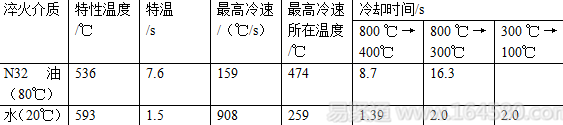
An evaluation criterion has been proposed: the average cooling rate of 400 ° C → 150 ° C measured by SH/T0220 is 120 ° C / s, which is equivalent to the cooling speed of ISO 9950 at 300 ° C, 50 ° C / s, and the average speed of 35 ° C / s is equivalent to 300 At °C, the cooling rate is 20 ° C / s.3. JB/T 7951 standard interpretation and evaluation According to JB/T 7591, there are 7 parameters for quenching medium cooling performance, which are characteristic temperature and special temperature seconds, the highest cooling rate and its position and cooling time (800 ° C →400 ° C, 800 ° C → 300 ° C, 300 ° C → 100 ° C).
The cooling performance data of N32 oil and water are shown in Table 1-5.Table 1-5 Cooling performance of N32 oil and water (JB/T 7951)
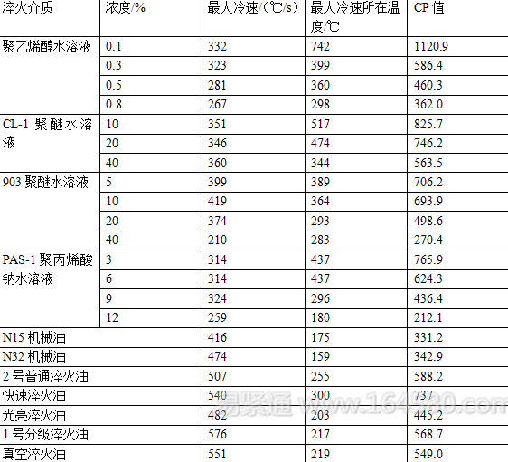
4. In the appendix A of the secondary square degree method JB/T 6955-93 "Technical requirements for heat treatment commonly used quenching medium", the cooling performance of common quenching medium is determined according to the original GB9449, and their maximum cooling rate and its temperature are given. If the quadratic degree per second method is used, the formula for calculating the CP value of the quenching oil and the organic quenching agent is as follows.
CP = 0.00455 × maximum cooling rate × maximum cooling rate temperature The tendency of organic quenching to cause cracking in the low temperature zone is not specified in Appendix A of JB/T6955. It is recommended to give an average of 300 °C → 200 °C given in the appendix. Cool speed. The average cooling rate of 300 ° C → 200 ° C is below 250 ° C / s, basically no cracking occurs, the data is shown in Table 1-6.Table 1.6 CP value of organic quenching agent and quenching oil (JB/T 7951)
Measures such as preventing and reducing external pollution of quenching oil, rational use and management of quenching oil, and regular testing of quenching oil cooling performance can slow down the deterioration and quenching of quenching oil, thereby improving the service life of quenching oil; deterioration and aging have occurred The quenching oil is regenerated to restore its performance and extend its service life.
Principles for selection of commonly used liquid media
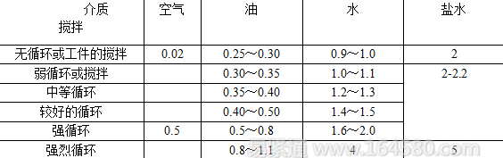
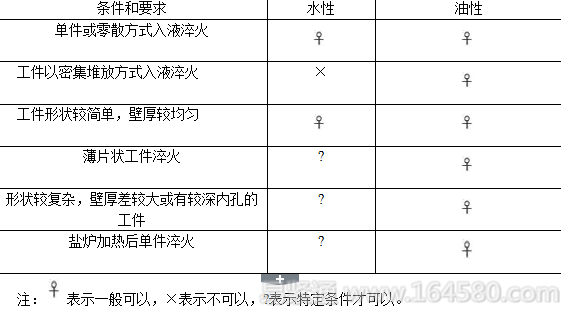
1. Common media selection points The characteristics and usage ranges of commonly used water and oil media are shown in Table 1-7 to Table 1-10. According to experience, the characteristics and uses of water and oily media are listed into four tables from the perspective of selection and use, for reference.Table 1-7 Requirements for workpieces and quenching methods for aqueous and oily media
Is the choice of aqueous medium or quenching oil? First of all, it should be considered from the treated steel. Table 1-8 provides a rough selection principle.
Table 1-8 Comparison of steel grade adaptability of aqueous and oily media

After determining whether the oil or aqueous medium is selected, it is further determined which aqueous or oily medium to select. Tables 1-9 show the cooling rate grades and applicable steel grades for each type of aqueous medium. Table 1-10 shows Characteristics and uses of different quenching oils. Combine the contents of the four tables to determine which quenching medium to use.
Table 1-9 300 ° C cooling rate of water-based shoals and applicable steel grades
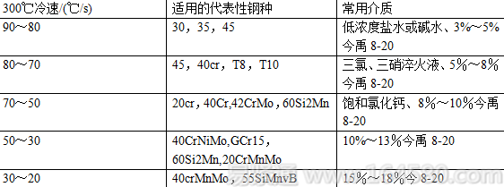
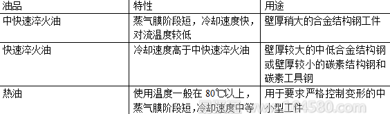
Table 1-10 Characteristics and uses of different quenching oils
2. Selecting the quenching medium according to the cooling characteristics Selecting the quenching medium should also take into account the requirements for the cooling characteristics, stability, operability, economy and environmental protection of the quenching medium. Among these requirements, the most important is the cooling characteristics of the quenching medium.
At present, the domestic and international methods are mostly measured by the international standard method (ISO 9950), and the cooling rate curve is used to characterize the cooling characteristics of the quenching medium. However, in the case of a specific workpiece, that is, the right steel grade, shape size and heat treatment requirements, it is considered that in the production site, a plurality of different steel grades, shapes, sizes, and heat treatment requirements are often quenched in a quenching tank.
While quenching the steel, the quenching and cooling process also causes a certain degree of quenching deformation of the workpiece. The traditional concept holds that the faster the quenching cooling, the higher the quenching hardness of the workpiece, and the greater the quenching deformation; the quenching cooling is slow, the quenching hardness is not high, and the quenching deformation of the workpiece is smaller. However, the actual situation is that most and relatively large quenching deformations are caused by slow quenching and insufficient hardening of the workpiece. Only a few and smaller quenching deformations are caused by faster quenching and higher quenching hardness.
According to the cracking, deformation and hardness of the specific workpiece after quenching, the cooling rate is divided into four zones in Figure 1-1, which are the excessively fast cooling zone, the moderate cooling zone, the insufficient cooling zone and the slow cooling zone. From the quenching hardness of the steel, a cooling rate value (referred to as the effect cooling rate at which the hardness of the quenched state can be obtained) can be determined from the drawing. The quenching effect of the cooling rate obtained by the workpiece in these areas is listed in Table 1-11. It can be seen that only in the second zone, that is, the moderate cold zone cooling, the desired quenching effect can be obtained after the workpiece is quenched.Table 1-11 Quenching effect of the cooling rate obtained by the workpiece in each area

The range defined by the highest and lowest values ​​of the speed at which the quenching deformation, cracking, and insufficient hardness are involved in the quenching deformation portion is called the "cooling speed band" at the time of quenching the workpiece. Depending on the actual workpiece and the quenching method, this cooling rate is wide and narrow. When the cooling obtained by each part on the workpiece is relatively uniform, the cooling speed band is relatively narrow; when the cooling obtained by each part on the workpiece is uneven, the cooling speed band is wider. The desired quenching effect can only be obtained if the cooling rate of the workpiece is completely dropped into its second cooling rate zone. Because, entering the area with the lowest cooling rate distribution curve to the left, there will be insufficient hardness and large quenching deformation; and when the maximum cooling rate distribution curve is in the right region, quenching will occur.
According to the principle of selection of the cooling rate distribution of quenching medium, there are five selection principles for quenching medium according to production experience.
(1) Steel with low carbon content The steel with low carbon content may precipitate proeutectoid ferrite. The quenching medium used should have a shorter vapor film stage and the temperature at which the highest cooling rate occurs should be higher. Conversely, for steels with a higher carbon content, the vapor phase of the quenching medium can be longer, and the temperature at which the highest cooling rate occurs should be lower. From the allowable maximum cooling rate curve, steel with a low carbon content allows a high cooling rate, and steel with a high carbon content allows a low cooling rate.
Figure 1-1 Dividing the end quenching curve into four zones according to the quenching cooling rate(2) Steel with poor hardenability and hardenability. The required cooling rate is fast; for steels with good hardenability, the required cooling rate is slower. At the same time, as the hardenability increases, the “C†curve of the steel will move to the lower right. Therefore, for the steel with poor hardenability, the temperature at which the medium has the highest cooling rate is required to be higher; and for the steel with good hardenability. The temperature at which the medium has the highest cooling rate is required to be lower. Some hardenable steels, too cold austenite are also prone to bainite transformation. To avoid the bainite transformation, it is also required to have a sufficiently fast cryogenic cooling rate. From the allowable maximum cooling rate values, steels with low hardenability allow higher cooling rates, while steels with higher hardenability allow lower cooling rates.
(3) Effective thickness of the workpiece When the workpiece is relatively thick, in order to obtain a sufficiently thick depth of the hardened layer, the quenching medium used should have a relatively fast cooling rate. Conversely, when the workpiece is thin, a quenching medium having a lower cooling rate can be used. From the allowable maximum cooling rate profile, the thick workpiece allows for a high cooling rate, and the thin workpiece allows a low cooling rate.
(4) Workpiece complexity First, from the allowable minimum cooling rate distribution curve, workpieces with complex shapes, especially those with inner holes or deep concave surfaces, should be used to reduce quenching deformation or to harden inner holes. Use a quenching medium with a shorter vapor film stage. Generally, the internal heat dissipation of the inner hole or the concave surface of the workpiece is slower than other parts, and the other parts of the workpiece are cold, and the first part enters the boiling stage to obtain rapid cooling, while the inner hole surface is still in the vapor film stage, and the cooling speed is still very slow. This difference in cooling may cause large quenching deformation of such workpieces and low hardness of the inner or concave quenching. The solution to this type of problem is to use a quenching medium with a shorter vapor phase. The same effect can be obtained by appropriately increasing the flow velocity of the medium in the inner hole portion. Conversely, for workpieces with a simple shape, a quenching medium with a slightly longer vapor phase can be used. From the allowable maximum cooling rate profile, the shape of the workpiece is allowed to have a low cooling rate, while the simple shape of the workpiece allows a high cooling rate.
(5) Allowing deformation The required deformation of the workpiece is small, the quenching cooling should have a narrow cooling speed zone, and the allowable deformation is large, and there can be a wide cooling speed zone. For the allowable cooling rate bandwidth, a medium that generally meets the quenching hardness requirements can be used. Among the methods for shortening the cooling rate of the workpiece, the simplest and most effective is to perform isothermal (or stepwise) quenching. The characteristics of the austempering medium should firstly be that the short phase of the vapor film and the change of the liquid temperature have little effect on the cooling rate. Secondly, the thicker workpiece should use the medium with faster cooling speed, while the smaller workpiece can use the cooling rate. Slower media.3. Quenching medium for a variety of workpieces at the same time. There are two kinds of workpieces to be quenched, A and B. Workpiece A has a moderate cooling rate distribution area. Workpiece B has another moderate cooling rate distribution zone. Put these two moderate cooling rate zones together. The overlapping parts of them are the moderate cooling rate distribution areas common to the two workpieces A and B. Both workpieces can be processed where the cooling rate curve can completely fall into the quenching medium of this common cooling rate distribution zone.
4. Selection principle of quenching oil Quenching oil is almost all mineral oil with higher flash point. The specific heat capacity of these oils is about l/2 of tap water, the thermal conductivity is about l/4 of tap water, and the convection start temperature is high. Moreover, the viscosity is much higher than that of water, so that the cooling rate of the quenching oil, especially the cooling rate in the low temperature stage, is much lower than that of water. For this reason, most workpieces are quenched in oil (including various fast oils) without the risk of quenching, and the usual concern is that the oil is cooled at a lower rate, making the thicker workpiece or the hardenability slightly lower. The steel grade does not reach the required quenching hardness and hardening depth, and thus large deformation occurs.
to this end. When quenching oil is used, it is often only considered from the lowest cooling rate profile of various workpieces.
Only when the cooling rate profile of the selected quenching oil can surround the lowest temperature cooling rate curve of these kinds of workpieces from the right side, the quenching of these kinds of workpieces can all obtain the three effects of quenching and cooling. It can be inferred that, in general, the shorter the vapor film stage of the selected oil, the lower the convection starting temperature and the higher the maximum cooling rate, the more the cooling rate curve of such oil may be from the right side. More, that is, the more applicable workpieces (steel types). This is the choice of quenching oil for a variety of workpieces.5. Selection principle of water-quenching quenching liquid The main danger of quenching in water (and aqueous solution) is quenching, and reducing the "300 °C cooling rate" of aqueous quenching liquid can reduce this danger. The lower the "300 ° C cooling rate" of the aqueous quenching agent, the stronger the ability to prevent quenching, and the more steel grades and workpieces are suitable. If the highest cooling rate profiles of a plurality of workpieces are drawn together, the common boundary line of the second zone can also be drawn, and the conclusion is also obtained. When the temperature of the water or aqueous solution is too high, such as usually above 60 °C, the quenching and cooling vapor film stage is significantly increased, and the vapor film is quite stable. At this time, the workpiece is quenched, and the cooling rate curve is easy to enter its III cooling rate from above. Zone, which causes insufficient quenching hardness and large deformation. Therefore, the use of aqueous quenching liquid should control the liquid temperature, generally the average liquid temperature does not exceed 60 ° C is appropriate. When the type of quenching liquid is determined, the cooling rate distribution during quenching of the workpiece can be changed by adjusting the quenching liquid concentration, the liquid temperature and the relative flow rate with the workpiece to meet the production needs.
Since there is a wide gap between the cooling rate distribution curve of ordinary oil and tap water, it is not enough to equip only ordinary oil and tap water. It is recommended to equip the general heat treatment workshop with the following four quenching liquids (tanks).
1 The ordinary oil is replaced by a quick quenching oil. The cooling characteristics should be: the quenching and cooling vapor film stage is short, the convection starting temperature is low, and the maximum cooling rate is large.
2 A water-soluble quenching liquid with stable performance and strong operability, its liquid temperature at 30 ° C, 300 ° C cold speed without agitation between 20 ~ 30 ° C / s.
3 A water-soluble quenching liquid with stable performance and strong operability, its liquid temperature at 30 ° C, 300 ° C cold speed without agitation between 50 ~ 70 ° C / s.
4 tap water. If the type of workpiece to be processed is not too much, a water-soluble quenching liquid with a cooling rate of 30 ° C to 50 ° C / s at 300 ° C can be used instead of two kinds of quenching liquids, that is, three quenching liquids are prepared ( groove).Maintenance and use of quenching media
1. Basic requirements for quenching medium maintenance The requirements are to prevent the medium from being contaminated, to ensure the normal operation of the cooling system, to control the liquid temperature as required, the aqueous medium to be frequently detected and controlled, and the cooling characteristics of the quenching medium to be periodically checked.
1 Before the new quenching medium is poured into the tank, especially in the old quenching tank, the quenching tank and the cooling system must be carefully cleaned. If you pour the oil into the cleaned tank, the oil that has sunk at the bottom of the tank, the carbon black sludge on the tank wall, and the oil that remains in the ridge system will be mixed into the new oil. It will cause a new tank of oil to be contaminated, and the quenched workpiece will be stained and cleaned, which is very difficult to clean.
2 If it is found that the quenching oil becomes easy to catch fire, find out the cause and solve it quickly. One of the reasons is that the oil has entered the water. Especially in the case of hot oil. The second reason is that the oil temperature measurement or display has a fault, and the actual oil temperature is much higher than the displayed oil temperature. In addition, the oil is mixed with a low flash point, a volatile oil, and it is easy to catch fire.
3 Prevent the carbon black in the heating furnace from contaminating the quenching oil. The carbon black generated in the carburizing and carbonitriding furnace enters the quenching oil, which may cause oil pollution. A small amount of carbon black gradually accumulates, first of all the damage of the brightening of the quenched workpiece, which subsequently affects the cooling characteristics of the oil. Carbon black particles are very small and are mostly suspended in oil, and it is generally impossible to separate them by filtration and sedimentation. It is the best solution to burn off the carbon black accumulated in the furnace at regular intervals.
4 Water-based and oil-based media have a certain life span, and each time the medium is replaced, the whole tank should be replaced. In addition to the oil used for quenching large workpieces, the service life of quenching oil at home and abroad generally does not exceed 3 to 5 years. If the sewage treatment is not done, the replacement time of the entire tank of the PAG quenching medium is generally less than 3 years.2. Anti-corrosion and anti-corrosion of PAG quenching liquid PAG quenching agent generally has a certain amount of anti-rust agent, and the aqueous solution is always higher than the anti-rust property of tap water. Therefore, there is generally no concern about the rust prevention of the quenching liquid. When it is found that the rust prevention is insufficient, a small amount of rust inhibitor can be added.
Corrosive changes in PAG quenching fluids often occur when the solution is first contaminated with organic matter such as oil and then unused for a longer period of time, especially during the hot summer months. The phenomenon of corruption is stinky and black. To date, there is no preservative to ensure that the contaminated quenching liquid that has been deactivated for a long time does not spoil. Tests have shown that blackening and odor do not affect the cooling characteristics of the quenching liquid, nor do they affect the concentration values ​​measured by the refractometer method using the viscosity method and the true concentration method. The air is brought in by the cyclic agitation in production, and the odor disappears after a while, and the solution is restored to its original color. This spoilage is caused by anaerobic bacteria, which have a bactericidal effect. Contact the quenching agent manufacturer to add a little bit of fungicide, which can kill bacteria, eliminate odor, and make the quenching liquid turn back to pale yellow.3. Measures to slow the change of quenching liquid at the production site 1 Extend the residence time of the workpiece in the quenching liquid after quenching and cooling, so as to dissolve the polymer adhered on the workpiece.
2 Further tap water cleaning of the workpiece just out of the quenching tank, and adding the washing water as supplementary water to the quenching tank.
3 Strengthen management to reduce the pollution of quenching liquid.
4 The conditional factory purchases a cooling characteristic tester by itself and uses the cooling characteristics to control the quenching liquid concentration.
5 Temporarily unconditional factories should regularly sample the quenching agent production plant for cooling characteristics testing and control the concentration with a cooling characteristic meter. Usually, in continuous production, it is best to take a sampling measurement every 3 months.
6 When the PAG quenching liquid used is used for a long time, the accumulation of pollution is high, the concentration measured by the refractometer is already quite high, and when the concentration measurement and the cooling characteristic control are difficult, the quenching liquid can be subjected to a “decontamination updateâ€. The treatment removes most of the pollutants and allows the active ingredients to remain. The treated quenching liquid can be used at a relatively low refractometer concentration, and the hardening effect and deformation prevention characteristics are comparable to the newly prepared quenching liquid.
Our company produces a vary of specifications of Glass Particles and glass-lumps which can be used in ordinary pavement of road to shorten braking distance effectively, to improve the warning role and to decelerate in advance to achieve safety. Pavement laid with this product will not peel off and maintain function well after a long time wheel friction.
It is also used in the decoration of building outer-walls and all kinds of ceramic. There is mainly 1-2 mm, 2-3 mm, 3-4 mm, 600-850 microns, 300-600 microns, 180-300, and less than 180 microns etc. as well customized specifications customers require.
The glass bead can be produced based on the standard of countries or areas, such as EN1423/1424, AASHTO M247, BS6088, JIS R3301 and KS L2521 etc.

Glass Particles
Glass Particles,Plastic Glass Particles,Color Fireproof Glass Particles,Crushed Colored Glass Particles
CHIYE GLASS BEAD (HEBEI) CO., LTD , https://www.chiyeglassbeads.com