Causes of decrease of power factor after photovoltaic equipment access
In recent years, China's photovoltaic grid-connected power generation projects have developed rapidly. According to statistics from the National Energy Administration, China's total PV installed capacity in 2014 was 10.5 GW, of which distributed 2.05 GW, total installed capacity in the first half of 2015 was 7.73 GW. Equation 1.04GW. With the rapid growth of installed capacity, the issue of photovoltaic grid-connected power generation and compatibility with existing power grids has become increasingly apparent. Especially for distributed photovoltaic grid-connected projects, generally the grid capacity is small, and compatibility issues are prone to occur. After the equipment is put into operation, the original power distribution factor of the distribution network drops below 0.9, causing adverse effects.
Here is a brief summary of the problem of power factor reduction and corresponding solutions for our company's PV inverters after they are connected at different sites. We also briefly talk about some understandings and suggestions for the design of distributed photovoltaic power plants.
First explain the power factor correlation formula:
η=P/S, where P is the active power and S is the apparent power.
S2=P2+Q2, Q is reactive power,
It can be known from the formula that the power factor is related to the system active power P and reactive power Q. When Q is zero, the power factor is 1. When Q is less than zero, the system absorbs reactive power and η is negative, when Q is greater than zero. When the system outputs reactive power, η is a positive value.
The following is a few examples to analyze the reasons for the decrease of power factor after photovoltaic equipment access.
1 Example 1
Schematic diagram As shown in Figure 1, a factory supplies power through a 10KV line, the capacity of the transformer is 2000kVA, the total capacity of the photovoltaic power generation equipment is 400kW, and the outlets are in the total 400V distribution cabinet. The factory originally installed a 400V three-phase common compensation SVC, and the current and voltage are sampled. Points are changed to 400V transformer under 10kV. Before the PV equipment was put into operation, the power factor of the system was stable at 0.9~0.95. After the photovoltaic equipment was put into operation, the power factor jumped between 0.7~0.9.
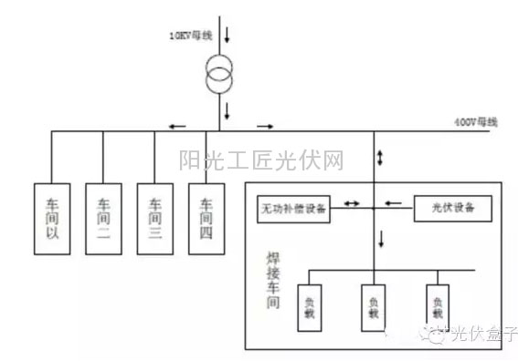
figure 1
Analysis: The grid structure of the distributed project is simple, and the PV grid connection point is close to the total transformer. There is only one SVC device. The problem elimination can be confirmed step by step. First, confirm the active power and reactive power of the PV system before accessing the grid through the factory grid point meter. The P is 700kW and the Q is 300kVA. After the PV equipment is connected, the P is 350kW~500kW and the Q is 310kVA. According to the data, there is basically no change in the reactive power of the PV system since the PV inverters are mostly operated at a unit power factor, and the output is basically full of power. The reason for the decrease in the power factor of the system is mainly the system consumption. Part of the active power is generated by the photovoltaic equipment. Providing that the active power absorbed from the grid is reduced, so the power factor is reduced according to the formula η=P/S.
It can also be seen from the data that before the photovoltaic equipment is not connected, the system reactive power Q is 300 kVA, and its value is too large. Generally, the initial power factor for the SVC equipment setting compensation is about 0.95, and the on-site power factor is lower than this value. , Suspected that the on-site SVC equipment is not operating properly. After on-site inspection, all SVC equipment capacitors are fully invested. It is suspected that the SVC equipment has insufficient capacity. Because the SVC equipment is a factory-owned equipment, and the usage time is long, inspection and maintenance are inconvenient. Abandon the scheme to increase power factor by adjusting SVC. The site will change the PV inverter output to reactive power given mode, adjust the inverter so that the total reactive output is 200 kVA, and after being put into use again, observe the data of the grid point. P is 350kW~500kW. Q is 100kVA and the power factor is kept above 0.95. At this point, the problem is solved.
2 Example 2
A factory supplies power through a 1000kVA capacity transformer. The total capacity of the photovoltaic equipment is 200kW. It is also equipped with SVC equipment. The PV system access power factor is between 0.95~0.97. After the PV equipment is connected, the power factor is between 0.3~0.7.
Analysis: Similarly, firstly, through the plant's total grid point meter, observe the active and reactive changes before and after the photovoltaic equipment is connected. Before access, P is 200 to 300 kW, Q is 30 kVA, and after access, P is 50 to 150 kW, and Q is 70 to 110 kVA. It can be seen from the data that the total reactive power of the PV system increases after the PV equipment is connected. After checking the SVC equipment, it is found that the capacitor group is not normally turned on, sometimes an alarm occurs, and all capacitors are cut out at the same time. Query the reactive power compensation controller manual The reason for the alarm is that the harmonic of the system current exceeds the standard. To protect the capacitor, cut it out. Through the search for relevant information on the Internet, the specific reason is because after the PV equipment is connected, because the inverter outputs with a unit power factor, and the current harmonic content is less, it can be considered that it provides part of the fundamental current and flows through the transformer. The fundamental current is thus reduced.
The harmonic current in the system does not change, so that at the sampling point of harmonic filtering and reactive power compensation, that is, on the low voltage side of the transformer, the relative content of current harmonics becomes larger, that is, the THD value calculated by the reactive power compensation controller. When it becomes larger, when this value exceeds the alarm value, the SVC device cannot perform reactive compensation normally. The on-site processing method is to modify the THD protection value of the reactive compensation controller to ensure that the THD can operate normally under relatively large THD. However, this solution has certain risks and may cause damage to the SVC capacitor group. If you want to fundamentally solve it, the best way is to replace the SVC with an APF device. You can also compensate for harmonics while compensating for reactive power. There will be no problem of harmonic violation. Through this project, we can see that although the PV access capacity meets the limitation of less than 25% of the capacity of its upper transformer, problems may still arise during actual operation. The actual power consumption of the user should be fully considered in the design, and the total power of the PV equipment can be It is configured to be half of the actual power used, so that the impact on the power grid is generally small, and all power distribution equipment can basically not be affected by normal operation.
3 Example 3
Schematic diagram As shown in Figure 2, a factory supplies power through a 10KV line, the transformer capacity is 2000kVA, and the 400V line is divided into 5 workshops. Each workshop is 400kVA and is equipped with SVC equipment. The total PV equipment is 400kW. The access point is welded. The lower part of the workshop is the 400V power distribution cabinet, and the SVC equipment sampling point of this workshop is also the distribution cabinet. Before the photovoltaic equipment was connected, the power factor of the 10kV grid-connected point was about 0.95. After the photovoltaic equipment was accessed, the power factor dropped to about 0.8.
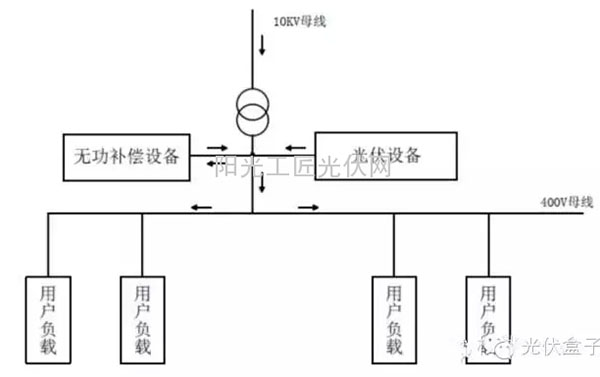
figure 2
Analysis: First of all, it can be clearly seen that the design of the project is irrational. Photovoltaic equipment is connected to a bus in the grid and the power consumption is almost equal to that of the workshop. The circuit is prone to countercurrent, and it has both compensation and acquisition equipment. Big impact. Because the PV is connected to the branch bus of the welding shop, the meter reading from the welding shop accessing the bus access point of the upper bus starts to analyze. Before the PV access, the P is 190~260kW and the Q is 30kVA. After the photovoltaic equipment is connected, P It is -50~-100kW and Q is -250kVA. After the photovoltaic equipment is connected, all capacitances of the SVC equipment in the welding shop are cut out and the power factor is displayed at -0.1 to -0.3. It is clear that the active power and reactive power detected by the SVC are incorrect, resulting in abnormal operation.
The photovoltaic equipment is disconnected from the system and all the SVC capacitors are manually cut out. The observed electricity meter shows that P is 190-260 kW and Q is 250 kVA. It is incorporated into the photovoltaic equipment one by one. It is observed that the active power P of the meter gradually decreases, and the Q is basically unchanged. When P decreases to a negative value, Q changes from 250kVA to -250kVA. The reason why the problem is found is because the reactive power compensation controller is not compatible with the reverse power, resulting in an erroneous measurement result and the wrong control capacitor being cut out. The total grid point power factor decreased. The specific solution is to replace the new model reactive power compensation controller, disable the controller's automatic detection wiring function, reconnect the photovoltaic equipment, observe the welding shop power meter display P is -50 ~ -100kW, Q is 30kVA, the total grid point power factor Back to normal.
4 Summary
Through the above three practical examples, methods for solving such problems can basically be summarized. First, the photovoltaic equipment is connected to the bus, the second is to confirm the sampling point of the reactive power compensation equipment on the bus, and finally, the cause of the problem is analyzed based on the bus total meter data. Sometimes the reasons are easy to find, but it is very difficult to solve them. When the entire construction of the project is completed and the network is replaced, or the branch road that would not have been reversed, there will now be a backflow. These problems can sometimes only take temporary measures or Compromise the low power factor, and only spend more money to purchase more powerful reactive power compensation equipment, both users and equipment manufacturers are unwilling to see, so design in the early stages of the project can fundamentally Avoid problems.
The first thing to be determined in the project design is capacity. According to the customer demand capacity, it is analyzed whether the existing lines, transformers, and network connection points meet the requirements. The total capacity of small-scale photovoltaic power plants should not exceed 25% of the maximum load in the power supply area of ​​the upper transformer in principle. Here, no more than 25% of the maximum load should be considered separately for all branches. Especially when each branch has an independent reactive power compensation device, a better design is to separate the photovoltaic devices in different branches and networks. The impact on a single branch can be minimized.
Second, the design needs to consider is the load situation in the overall bus or branch, for the load changes frequently and the power fluctuation of the branch should not be selected as the photovoltaic access point, photovoltaic equipment may increase the branch power fluctuations , Resulting branch voltage and frequency changes, in severe cases, will lead to inverter off the net, load damage, etc., at the same time line voltage, current harmonics may also be affected, resulting in harmonic sensitive equipment can not work properly.
In the design, it is advisable to know in advance the existing reactive power compensation or APF equipment in the user's power distribution network, and to make plans in advance for the possible impact of the PV equipment accessing the corresponding branch. Once there is a situation, the solution can be remedied. It is best to be able to understand the function and parameters of the relevant equipment in advance, and to conditionally test the performance and protection values ​​in advance.
The above points are some suggestions on the issues related to power factor in the design of distributed power stations. I hope to give you a reference in the power plant design. The examples are only some conclusions about specific projects, and it is inevitable that they have been overlooked. The situation may be different, but the specific issues must be analyzed in detail. If everyone has any good ideas in the power station design, please feel free to contact us.
CBN inserts is especially for sharpening and rough grinding of tungsten, tungsten and molybdenum and other high speed steels,
and super-finishing of difficult-to-machine heat-resistant steel workpieces and grinding of other steel quenching tools
CBN Insert,CBN Welding Tips,PCBN Insert Vendor,CBN Cutting Tools
OPT Cutting Tools Co., Ltd. , https://www.optdiamondtools.com